The best way to learn how to use Connexis is to build a small distributed application that uses it. This tutorial will take you through the steps that are required to create, build and execute a Connexis-enabled application. The only prerequisite for following this tutorial is that you have Model RealTime with Connexis installed (note that Connexis is an optional installation component that is not installed by default).
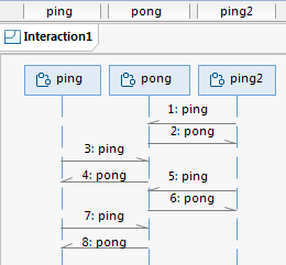
The application to be created in this tutorial is a simple "ping pong" application. Each client sends a "ping" message to the server, and the server responds with a "pong" message. The sequence diagram below shows the messages that are sent between the Ping (client) capsule instances and the Pong (server) capsule instance.
Registration is accomplished using the Locator Service. The necessary command line options for starting the applications are also presented.
This application is created in two iterations:
Iteration 1: Creating the Application Model
Creates the basic architecture using wired ports to connect the Ping and Pong capsules. This also involves a third capsule which acts as the container for the Ping and Pong capsules.
Iteration 2: Use Connexis to Make the Application Distributed
Makes modifications in the application so that Ping and Pong communicate through unwired ports that make use of Connexis connections.
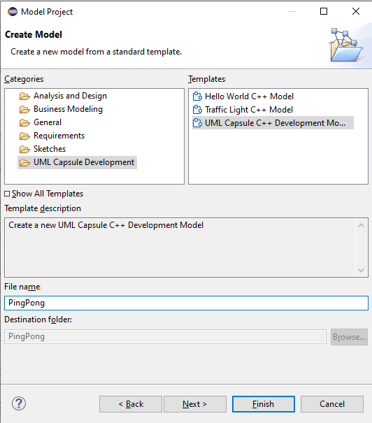
Start by creating a new model project (File - New - Model Project). Give the new project the name "Connexis_PingPong".
Find the created project in the Project Explorer, and select the top PingPong package. Use the context menu command Add UML - Package to create four packages under the PingPong package.
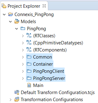
Using packages for organizing the elements of an application may not be necessary for a small and trivial application like this one, but for larger applications it can help to group related elements into packages.
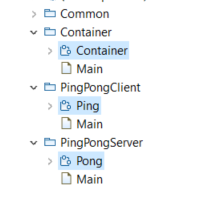
Select the PingPongClient package and create a Ping capsule in it. (Add UML - Capsule in the context menu)
Create a Pong capsule in the PingPongServer package.
In this application, the Ping capsule plays the role of the client. It is referred to as the client because it only manages a single connection. The server side of the application is responsible for managing multiple connections (one for each client it is connected to). The Pong capsule plays the role of the server in this application. Note that in a real-world distributed application it is not uncommon that the same object both can play the role of client and server, for different communication scenarios. However, in this simple application Ping capsule instances are always clients, and a single Pong capsule instance is the server.
Create a Container capsule in the Container package.
You now have all three capsules needed for this application:
Now it's time to define the communication between the Ping and Pong capsules, by creating a protocol. Select the Common package and use the context menu command Add UML - Protocol to create a protocol called "PingPong".
Create two events in the protocol; an In Event called "pong" and an Out Event called "ping".
The convention we use here is to define the protocol from the perspective of the client. That's why "pong" is an In Event, because it will be received by the client, and "ping" is an Out Event because it will be sent by the client. Note that this way of defining a protocol is just a convention. It also works to define a protocol from the perspective of the server. The most important is that you are consistent throughout the whole application, to make the model easier to understand. However, a benefit with defining protocols from the perspective of the client is that you then only need to conjugate one port (the one in the server), while all client ports can remain non-conjugated. There are usually more client ports than server ports, which is why this convention means less modeling effort.
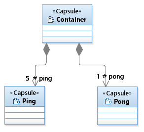
Rename the Main class diagram in the top PingPong package to "Architecture". Drag and drop all three capsules onto the class diagram and create composition associations from Container to Ping and Pong. By doing so you add two capsule parts ("ping" and "pong") in the Container.
Set the multiplicity of the "ping" capsule part to 5. Keep the "pong" capsule part multiplicity unchanged. This means we will have 5 Ping clients and 1 Pong server in the application.
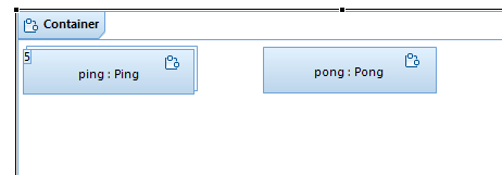
If you open the structure diagram of the Container capsule, you can see the capsule parts there too.
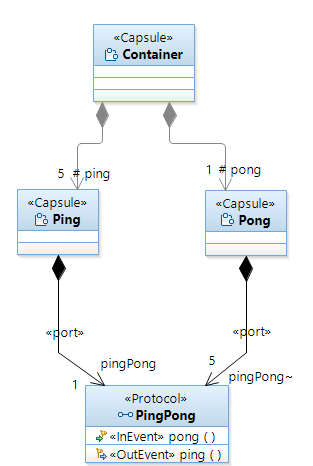
Create a port in both the Ping and Pong capsule. This can be done in many ways, for example by dragging the PingPong protocol onto the Architecture class diagram and then creating composition associations from Ping and Pong to the PingPong protocol. Keep the default port name that is derived from the name of the protocol ("pingPong").
Set the multiplicity of the port in the Pong capsule to 5 so that it can connect to 5 different Ping clients. Also, using the Properties view, mark that port as conjugated. This swaps the meaning of In Events and Out Events in the protocol so that Pong can receive the "ping" Out Event and send the "pong" In Event.
Create a port "log" in both the Ping and Pong capsules. Type this port with the predefined Log protocol. The Ping client will use this port to write a log message when it receives the "pong" event from the server, and the Pong server will write a log message when it receives the "ping" event from a client. Note that contrary to the "pingPong" port, these ports should not be service ports, so unmark the Service checkbox in the Properties view. A non-service port is not part of the communication interface of a capsule, and can only be used by the capsule itself.
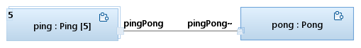
To let the Ping and Pong capsules communicate we need to connect the "pingPong" ports. For now we will connect them with a connector, but in the next section (Iteration 2: Use Connexis to make the application distributed) we will instead make the ports non-wired and use Connexis for establishing the communication path. Create the connector in the structure diagram of the Container capsule.
Select the Ping capsule, either in the "Architecture" class diagram or in the structure diagram of the Container capsule. Perform the command Open State Machine Diagram from the context menu to open the state machine of the Ping capsule. It has a default simple state machine just consisting of one state and an initial transition.
Rename the state to "ready".
Select the initial transition and use the Code view to enter the following effect code:
pingPong.ping().send();
This means that as soon as an instance of the Ping capsule is created, and its state machine starts to execute, it will send the "ping" event on the "pingPong" port.
Use the context menu command Add UML - Transition to create an internal transition for the "ready" state.
Use the Triggers page in the Properties view to create a trigger for this transition. The transition should trigger when the "pong" event is received on the "pingPong" port. Also rename the transition to "pong". To make the state machine readable it can often be good to name the transition according to the event that triggers it, at least when it can only be triggered by one event as in this case.
Use the Code view and enter the following effect code for the "pong" transition:
log.log("received a pong");
log.commit();
pingPong.ping().send();
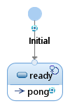
The Ping state machine should now look like this:
Why did we create "pong" as an internal transition, instead of drawing an external transition line from the "ready" state and back to itself? Because we want the state machine to stay in the "ready" state when it handles the "pong" event. This both makes the state machines easier to understand, the state chart diagram easier to draw, and also the generated application to run slightly faster (no need to first exit the state and then enter it again).
log.log("received a ping");
log.commit();
rtport->pong().reply();
Here we have used "rtport" which for each transition effect code refers to the port on which the event that triggered the transition was received. "rtport" is mainly useful when you want to reply on a received event on the same port. In that case you don't have to refer to the port by its name. Feel free to instead send the event in the same way as was done in the Ping state machine if you think it makes the code more readable.
To build and run the model you have created, you need a transformation configuration (TC). This is a file that contains all build settings and other properties that control how the model is transformed into an executable application. Your model project contains a default transformation configuration called "Default Transformation Configuration". It contains many useful default settings, but some updates are needed before it can be used for building your application.
Double-click on "Default Transformation Configuration" to open the TC editor. Set the following TC properties:
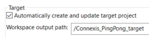
On the Main tab, click "Automatically create and update target project" and specify a workspace path for where to create the CDT project with generated C++ files. For example:
On the Code Generation tab, set the "Top capsule" property to the Container capsule. This specifies the capsule that will be incarnated when the application starts up.
On the Target Configuration tab, set the "TargetRTS configuration" property to match your target platform (OS and compiler). Also specify the make dialect using the "Make type" property.
Save the TC and build it by using the context menu command Build. C++ code will be generated, and compiled and linked into an executable. The executable is placed in the "default" folder of the specified target project, and is called "executable".
Run the application by using the TC context menu command Run As - RealTime Application. After a short while you should see the log message printouts in the Console view:
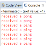
These printouts show that your ping pong application works correctly. Each of the 5 clients sends a "ping" and the server replies with a "pong" to each of them. Now it's time to convert this monolithic application into a distributed application using Connexis.
Before converting the sample PingPong model built in Iteration 1 to use Connexis, you may want to copy the project and paste it as a "PingPong_Iteration1" project. Thereby you can compare the models for the distributed and monolithic PingPong applications later.
The first thing we need to do, in order to make our application use Connexis, is to replace the wired ports with non-wired ports. Connexis manages connections that are established between unwired ports. Unwired ports are ports whose connections are defined at run-time. Unlike wired ports, unwired ports cannot be connected by connectors. The connections established between unwired ports can also be removed and re-established at run-time. Hence, unwired ports allow for more dynamic connections in an application. Unwired ports can be used also in non-Connexis applications when you need more dynamic connections in an application. However, only use them when necessary since the main drawback with non-wired ports is that you no longer can see the connection paths graphically in composite structure diagrams. This could make an application harder to understand.
Open the structure diagram of the Container capsule and delete the connector by right-clicking on it and performing the Delete from Model command.
Convert the "pingPong" ports of the Ping and Pong capsule to become unwired ports. You can do it from the Properties view by unmarking the "Wired" checkbox.
Mark the "Publish" property for Pong's port. This makes it a Service Provision Point (SPP), i.e., a capsule port for a server that publishes a service through the port. Also set the "Registration Kind" property to "Application". This means that the TargetRTS will not automatically attempt to register the port to establish connections at run-time. Instead we will perform the registration programmatically using transition code.
For Ping's port we leave the "Publish" property unset. This makes it a Service Access Point (SAP), i.e. a capsule port for a client that accesses a service through the port. Also for this port we set the "Registration Kind" property to "Application" to let us manage the registration of the port from code.
When a matching SAP and SPP port have been registered, Connexis can establish a dynamic connection between the ports. Our responsibility as application developers is not to establish the actual connection, but only to register a port when its owning capsule is ready to start communicating. This simplifies our code significantly, since we don't need to handle the actual work of setting up (or removing) connections, which in case of a distributed application can be a non-trivial task.
For Ping's port we also need to set the "Notification" property. This is necessary so that the Ping capsule will be notified (by means of the rtBound event) when its port get connected to Pong's port at run-time.
It is common to only have the "Notification" property turned on for SAP ports on clients, and not on SPP ports on servers. This is because a server usually just waits for incoming events from clients, and replies to them when they arrive. A client, on the other hand, needs to know when the server is available, since it cannot make the server request until then. However, in case a server needs to somehow keep track of the connected clients, it too may benefit from setting the "Notification" property.
Up until now we have only used standard UML-RT concepts to create our model. Now it's time to start using Connexis.
Import the Connexis model library to your workspace (File – Import – Existing Projects into Workspace). The project to import is located in the Model RealTime installation under rsa_rt/Connexis/DCS.
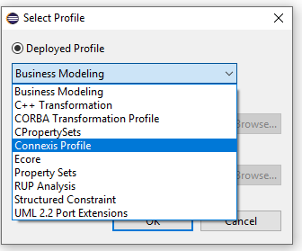
Select the top-level PingPong package. Use the Profiles tab in the Properties view to apply the Connexis profile. You find it in the Deployed Profiles drop down.
Using the Connexis profile is not mandatory but it makes it easier to add the necessary Connexis elements to your model. When you apply stereotypes from the Connexis profile, needed Connexis elements will be automatically added to your model.
Select the Ping capsule. Use the Stereotypes tab in the Properties view to apply the stereotype "Connexis Feature" to the capsule.
When this stereotype is applied to the capsule, a capsule part is automatically added to it. It is typed by RTDBase from the Connexis library. This capsule part exposes various Connexis services for the capsule.
Set the "RTD InitStatus Port" property of the "Connexis Capsule" stereotype to True.
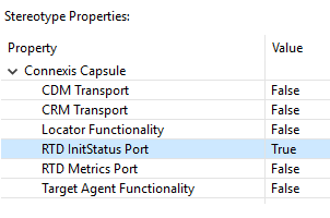
When this stereotype property is set to True, an RTDInitStatus port is automatically added to the capsule. The purpose of this port is to notify the capsule when the Connexis library has been properly initialized and is ready to be used. It is an SAP port that at run-time will be connected to the corresponding SPP port on the RTDBase capsule. The port's Notification property is enabled which means the capsule can wait for the rtBound event to arrive on the port. Before it arrives Connexis is not ready to be used, and any attempt to use it will fail.
Now repeat the same steps for the Pong capsule. First apply the "Connexis Feature" stereotype and then set the "RTD InitStatus Port" property to True.
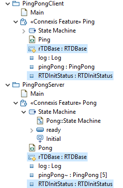
Confirm in the Project Explorer that the Ping and Pong capsules now look as shown below (elements that were added automatically by the Connexis profile have been selected):
As you may have already guessed, the next step is to update the state machines of Ping and Pong to wait for the rtBound event on the RTDInitStatus ports.
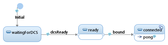
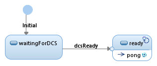
Open the Ping state machine and add a new state "waitingForDCS". The capsule will wait in that state until Connexis has been initialized. Delete the old initial transition and create a new one that instead targets the "waitingForDCS" state. Then add a transition "dcsReady" from the "waitingForDCS" state to the "ready" state. Finally add a trigger for the rtBound event on the RTDInitStatus port for this transition.
The Ping state machine should now look like this:
Repeat the same procedure for the Pong state machine.
Once Connexis has been initialized, it can establish a connection between the pingPong ports of Ping and Pong. Remember that these ports now are unwired and with the "Registration Kind" property set to "Application". This means they are no longer connected immediately when the capsule instance is created. Instead, they will be connected programmatically, and this can only be done when Connexis has been initialized.
Open the Ping state machine and add a new state "connected". Add a transition between the "ready" state and the "connected" state and call this transition "bound". Add a trigger for the transition so it triggers when rtBound arrives on the pingPong port.
Select the "bound" transition and use the Code view to enter the following effect code:
pingPong.ping().send();
This was the code we previously had in the initial transition. Note that the introduction of Connexis caused us to delay the sending of this event until we are sure that Connexis has been initialized and the pingPong port has been bound to the Pong server.
Move the "pong" transition from the "ready" state to the "connected" state. Unfortunately it is not possible to simply move this transition from one state to another in a diagram nor in the Project Explorer (a future version of Model RealTime will hopefully support this). Instead you have to temporarily make the transition external (in the Properties view), then move each transition line endpoint from the "ready" to the "connected" state, and finally make the transition internal again.
The Ping state machine should now look like this:
The connection of unwired ports in your model uses the registration string that has been specified for the ports (using the "Registration Override" property). If no registration string is specified, it defaults to the name of the port. Without Connexis the ports are always connected within the same TargetRTS. In this case you can use any registration string as long as the same string is used for SAP and SPP ports. However, when Connexis is used there are three different ways how the lookup of a registered port can be done:
Locally
This is the same as if Connexis is not used, i.e., a registered target port is looked for in the current TargetRTS.
Explicit address
Here, the registration string contains an explicit address of where the application with the target port is located. Connexis will only look for the port in that specific location.
Locator
Here, the Locator service is used to find the location where the target port should be searched.
The format of the registration string determines which of these three ways that will be used. For our PingPong application we will use the Locator, where the registration string has the following syntax:
dcs:/pingpong
The name "pingpong" could of course be changed to anything, as long as the SAP and SPP ports agree on the same name. It should also be noted that Connexis supports certain parameters to be specified in the registration string, for example to set which transport protocol that should be used, but it is beyond the scope of this tutorial to go into those details.
Now let's add the code for registering the pingPong ports.
Open the Ping state machine. Select the "dcsReady" transition and type the following effect code in the Code view:
if (!pingPong.registerSAP("dcs:/pingpong")) {
    log.log("Ping registration failed");
    log.commit();
}
Open the Pong state machine. Select the "dcsReady" transition and type the following effect code in the Code view:
if (!pingPong.registerSPP("dcs:/pingpong")) {
    log.log("Pong registration failed");
    log.commit();
}
As the final step, before our model is ready to be built, we must specify a couple of more configuration settings for Connexis. We need to decide where the Locator service should be placed. Ping and Pong will run in their own executables and any of these could contain the Locator service. We choose to place it in the server application, i.e. in Pong.
Select the Pong capsule and go to the Stereotypes tab in the Properties view. Set the "Locator Functionality" property of the "Connexis Capsule" stereotype to True.
When this stereotype property is set to True the "rTDBase" capsule part is renamed to "rTDBaseLocator" and retyped to RTDBaseLocator from the Connexis library. This capsule implements the Locator service. Note that it inherits from RTDBase so we still keep all the functionality provided by that capsule.
And finally, we need to specify which transport to be used for sending the messages between the applications. Connexis provides two kinds of transports out of the box, CRM and CDM. Let's use CDM for our application.
Select the Ping capsule and go to the Stereotypes tab in the Properties view. Set the "CDM Transport" property of the "Connexis Capsule" stereotype to True.
Repeat the same step for the Pong capsule.
The TC we used previously for building the application can not be used for building the updated model since it builds everything into a single application. We must create two new TCs, one for building an executable with Ping and one with Pong.
Right-click on the "Transformation Configurations" virtual folder and perform the command Create Transformation Configuration File. Do this twice, and call the first TC file "Ping.tcjs" and the second one "Pong.tcjs". Then set the following TC properties using the TC editor:
On the Main tab, set the "Sources" property. Ping.tcjs should have it set to the packages PingPong::Common and PingPong::PingPongClient while Pong.tcjs should have it set to the packages PingPong::Common and PingPong::PingPongServer.
Also on the Main tab, mark the "Automatically create and update target project" checkbox and specify the "Workspace output path" for the target projects. Call it "/Pingtarget" for Ping.tcjs and "/Pongtarget" for Pong.tcjs.
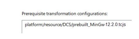
On the References tab, add a prerequisite TC for linking with the prebuilt Connexis library that is available in the Connexis library model. Choose one that matches the target platform you build for. For example:
On the Code Generation tab, set the top capsule. Set it to the Ping capsule for Ping.tcjs and the Pong capsule for Pong.tcjs.
On the Target Configuration tab, set the same target specific properties as you used for the "Default Transformation Configuration" previously. Also set the "Executable name" property to Ping$(EXECEXT) for Ping.tcjs and Pong$(EXECEXT) for Pong.tcjs.
Save the TCs and build them by using the context menu command Build.
Open two command prompts and run the built executables. Start Ping.exe like this:
Ping.exe -CNXep=cdm://localhost:7777 -CNXlpep=cdm://localhost:8888
-URTS_DEBUG=quit
Start Pong.exe like this:
Pong.exe -CNXep=cdm://localhost:8888 -CNXlp -URTS_DEBUG=quit
The -CNXep command-line option specifies the "endpoint location" for the executable (i.e. the machine where it is running and the port it listens to). The -CNXlp option specifies that the PongApp will act as the primary locator. The -CNXlpep option informs the PingApp of the location of the primary locator. For more information about Connexis command-line options, refer to Connexis Command Line Options.
A short while after both applications have been started you should see output that indicates a successful sending of ping and pong between the two executables using Connexis:
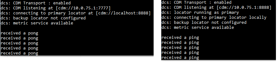
Congratulations, you have now built your first distributed application using Connexis.
If you want, you can now experiment with running the executables on different machines. The only change that is needed for this is to use different command-line options where "localhost" is replaced with the machine name or IP address.
The PingPong model you just have built is of course very simple, but it still illustrates the main Connexis concepts and workflow. We started by creating a regular UML-RT model, with wired ports and connectors, and then converted it to a Connexis model using unwired ports that are registered programmaticaly. In a more realistic scenario it is often known beforehand that the application needs to be distributed, and in that case you would of course build it using Connexis already from the beginning.
Note that only the ports that connect the distributed parts of the application need to be unwired. Within each application it is recommended to use wired ports and connectors since they allow the communication paths to be visually shown in structure diagrams.
In general, it's a good idea to think about distribution aspects already when designing the application, mainly because of performance. Many of the performance issues that you may encounter in a distributed application are a direct result of not partitioning your model properly. Remember that intra-thread messages are faster than inter-thread messages, which are faster than inter-process messages, which are faster than inter-machine messages.
In the tutorial we used the Locator service to resolve the registration strings for the unwired ports. If the nature of your application is such that you know the names of the endpoints that you want to communicate with (either through the use of an algorithmic mapping or by reading a configuration file), then explicit endpoint names can be used in the registration strings of the unwired ports in the model. This avoids the need to use the Locator service and therefore improves performance.
Finally, the beauty of Connexis is that once your unwired ports have been registerred, and Connexis has established the connections between them, then your application can send and receive messages on these ports in exactly the same way as with normal ports.